
LTE Radio Protocol Architecture
The radio protocol architecture for LTE can be separated into control plane architecture and user planearchitecture as shown below:
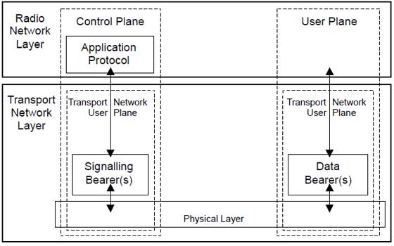
At user plane side, the application creates data packets that are processed by protocols such as TCP, UDP and IP, while in the control plane, the radio resource control (RRC) protocol writes the signalling messages that are exchanged between the base station and the mobile. In both cases, the information is processed by the packet data convergence protocol (PDCP), the radio link control (RLC) protocol and the medium access control (MAC) protocol, before being passed to the physical layer for transmission.
User Plane
The user plane protocol stack between the e-Node B and UE consists of the following sub-layers:
- PDCP (Packet Data Convergence Protocol)
- RLC (radio Link Control)
- Medium Access Control (MAC).
On the user plane, packets in the core network (EPC) are encapsulated in a specific EPC protocol and tunneled between the P-GW and the eNodeB. Different tunneling protocols are used depending on the interface. GPRS Tunneling Protocol (GTP) is used on the S1 interface between the eNodeB and S-GW and on the S5/S8 interface between the S-GW and P-GW.
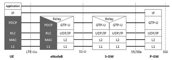
Packets received by a layer are called Service Data Unit (SDU) while the packet output of a layer is referred to by Protocol Data Unit (PDU) and IP packets at user plane flow from top to bottom layers.
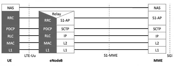
Control Plane
The control plane includes additionally the Radio Resource Control layer (RRC) which is responsible for configuring the lower layers.
The Control Plane handles radio-specific functionality which depends on the state of the user equipment which includes two states: idle or connected.
| Mode | Description |
|---|---|
| Idle | The user equipment camps on a cell after a cell selection or reselection process where factors like radio link quality, cell status and radio access technology are considered. The UE also monitors a paging channel to detect incoming calls and acquire system information. In this mode, control plane protocols include cell selection and reselection procedures. |
| Connected | The UE supplies the E-UTRAN with downlink channel quality and neighbor cell information to enable the E-UTRAN to select the most suitable cell for the UE. In this case, control plane protocol includes the Radio Link Control (RRC) protocol. |
The protocol stack for the control plane between the UE and MME is shown below. The grey region of the stack indicates the access stratum (AS) protocols. The lower layers perform the same functions as for the user plane with the exception that there is no header compression function for the control plane.
LTE Protocol Stack Layers
Let's have a close look at all the layers available in E-UTRAN Protocol Stack which we have seen in previous chapter. Below is a more ellaborated diagram of E-UTRAN Protocol Stack:
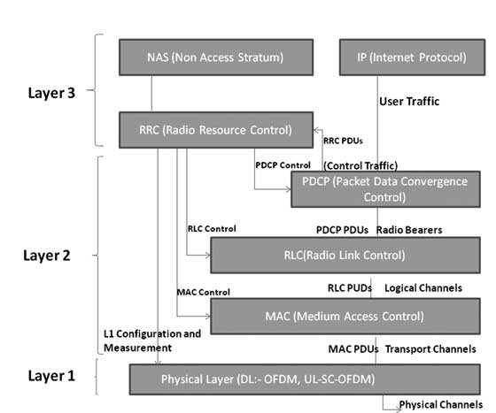
Physical Layer (Layer 1)
Physical Layer carries all information from the MAC transport channels over the air interface. Takes care of the link adaptation (AMC), power control, cell search (for initial synchronization and handover purposes) and other measurements (inside the LTE system and between systems) for the RRC layer.
Medium Access Layer (MAC)
MAC layer is responsible for Mapping between logical channels and transport channels, Multiplexing of MAC SDUs from one or different logical channels onto transport blocks (TB) to be delivered to the physical layer on transport channels, de multiplexing of MAC SDUs from one or different logical channels from transport blocks (TB) delivered from the physical layer on transport channels, Scheduling information reporting, Error correction through HARQ, Priority handling between UEs by means of dynamic scheduling, Priority handling between logical channels of one UE, Logical Channel prioritization.
Radio Link Control (RLC)
RLC operates in 3 modes of operation: Transparent Mode (TM), Unacknowledged Mode (UM), and Acknowledged Mode (AM).
RLC Layer is responsible for transfer of upper layer PDUs, error correction through ARQ (Only for AM data transfer), Concatenation, segmentation and reassembly of RLC SDUs (Only for UM and AM data transfer).
RLC is also responsible for re-segmentation of RLC data PDUs (Only for AM data transfer), reordering of RLC data PDUs (Only for UM and AM data transfer), duplicate detection (Only for UM and AM data transfer), RLC SDU discard (Only for UM and AM data transfer), RLC re-establishment, and protocol error detection (Only for AM data transfer).
Radio Resource Control (RRC)
The main services and functions of the RRC sublayer include broadcast of System Information related to the non-access stratum (NAS), broadcast of System Information related to the access stratum (AS), Paging, establishment, maintenance and release of an RRC connection between the UE and E-UTRAN, Security functions including key management, establishment, configuration, maintenance and release of point to point Radio Bearers.
Packet Data Convergence Control (PDCP)
PDCP Layer is responsible for Header compression and decompression of IP data, Transfer of data (user plane or control plane), Maintenance of PDCP Sequence Numbers (SNs), In-sequence delivery of upper layer PDUs at re-establishment of lower layers, Duplicate elimination of lower layer SDUs at re-establishment of lower layers for radio bearers mapped on RLC AM, Ciphering and deciphering of user plane data and control plane data, Integrity protection and integrity verification of control plane data, Timer based discard, duplicate discarding, PDCP is used for SRBs and DRBs mapped on DCCH and DTCH type of logical channels.
Non Access Stratum (NAS) Protocols
The non-access stratum (NAS) protocols form the highest stratum of the control plane between the user equipment (UE) and MME.
NAS protocols support the mobility of the UE and the session management procedures to establish and maintain IP connectivity between the UE and a PDN GW.
No comments:
Post a Comment